

Landsec’s 21 Moorfields development – over a live Tube station – has employed numerous digital tools to deliver a complex structural design and construction methodology

Bridging a 55m-span over Moorgate Station, the 17-storey 21 Moorfields development is a new landmark feat of engineering for the City of London.
The 60,000 sq m commercial building project, which straddles three Tube lines, Underground sidings and Crossrail, required a complex structural design – which was developed in conjunction
with the build strategy – aided by cutting edge digital tools.
The approach to the Landsec project was conceived and delivered by the team of engineers at Robert Bird Group (RBG), working with architect Wilkinson Eyre and contractor Sir Robert McAlpine. Logistically and technically, RBG had to take a holistic view of the design and construction process, bringing its in-house construction engineering division to work with the main design team from concept stage.
“The consideration of buildability within the permanent structural system was fundamental to our design philosophy,” says RBG project director Nick Cole.
“Where possible, we always integrate temporary works or smart construction sequencing into the structural design to simplify construction”
From the outset, it was non- negotiable that Moorgate Station had to remain operational throughout demolition and construction activities. Other constraints the team had to negotiate included the limited loading capacity of the slab which forms the existing station roof, which had to support construction activities, including cranes, plus safely constructing the structural frame directly over the live station.
For these reasons, RBG decided to use an early construction methodology and erection sequencing approach with the structural design, plus integrated erection stress analysis. This approach, usually applied at later project stages, allowed the team to understand risk, cost and programme for the works, and validate the construction methodology and programme with LandSec and Transport for London.
The superstructure design has been shaped by the tight location and the limitations of the station roof slab. While efficient in the permanent condition, the capacity of the roof required an alternative support system to enable the construction of the steel structure.

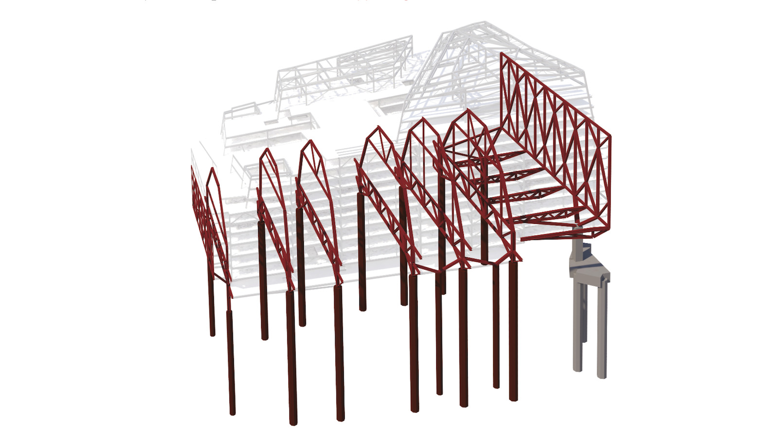
The structural design features a series of six 10-storey-high steel arches. Each of these incorporates a two-storey ‘launching truss’ at the base of the building. These act as temporary works during construction, but will then be integrated as architectural features in the finished building at lower levels.
Otherwise, the superstructure is conventional in form, using steel columns to support cellular beams up to 21m long, which work compositely with metal-decked lightweight concrete floors. The structure rests on 15 2.4m diameter piles – among the highest loaded ever driven in London – which had to be threaded delicately through numerous underground constraints, to depths of 60m.
Project team
Project: 21 Moorfields
Client: Landsec
Consulting engineer: Robert Bird Group
Architect: Wilkinson Eyre
Main contractor: Sir Robert McAlpine
Steel frame contractor: William Hare
The erection stress analysis for the above-ground structure used a staged construction finite element model – created in analysis software Midas – to prove the concept and identify approximate costs, which allowed for the omission of significant temporary works, according to RBG.
“Where possible, we always integrate temporary works or smart construction sequencing into the structural design to simplify construction,” explains Cole. “This may result in a slightly heavier permanent structure but always results in overall programme and cost reductions.”
As the concept developed, more details about the construction methodology and erection sequencing were layered into the design. Some of the steel members were too heavy for the crane capacity and splices were required for the trusses, arches and 21m-span secondary beams.
This is where the digital tools started coming into their own.
“An automated script, written in [programming language] Dynamo, within Revit flagged non-compliant members through the design and construction planning process, providing certainty on the number of splices, piece count and key architectural connection locations and details,” explains Cole.
The steel erection sequencing model was also developed in detail. In collaboration with William Hare, the steel frame contractor, working under a pre-construction service agreement (PCSA) prior to main contract award, RBG coordinated a sequence that would reduce the construction programme with as few constraints to follow on trades as possible.

What is erection stress analysis?
How simulations can help understand performance
Erection stress analysis forms an essential part of early construction methodology and erection sequencing for structures where stresses and deformations generated by the erection process can lead to inferior structural performance, increased frame material or excessive temporary works.
The process involves simulating the incremental construction sequence within the structural analysis model to understand the performance of
the building during construction.
The screenshot from Strand7 shows the model for 21 Moorfields.
RBG linked this sequencing model, created using finite element analysis software Strand7, to visualisation tools 3ds Max, producing both stills and video renders of the developed construction sequence. This was used to inform the main contract tender.
“Extracting our analysis data into a tangible and accessible format improves coordination, communication of risks and enhances the contractors’ understanding of the structural frame constraints,” says Cole.
As the main contractor Sir Robert McAlpine, also working under a PCSA, developed the final construction sequence and temporary works schemes, RBG developed the erection stress analysis model to include all temporary works members, providing a model that simulated the construction method as close as possible.
The tender process identified that it would be necessary to jump tower cranes off the station roof and onto the structural frame, loading the launching trusses.
“As a result, the erection sequencing model was adapted and assessed to identify member and connection overloading, allowing the necessary steps to be taken within the fabrication process prior to work starting on site,” says Cole.
With such a complex structural design, the project team needed to understand how movements in the frame would develop once construction work started, with Sir Robert McAlpine’s formal appointment in October 2018. To help with this, RBG uses visual programming software Grasshopper to link its erection stress analysis model with 3D design application Rhino.
“Construction movements are a significant issue due to the complex interaction between the launching truss and arch systems, which work independently as the frame is erected to level 10, and together thereafter,” explains RBG’s project lead at 21 Moorfields, Chris Papanastasiou.
“Issues such as welded nodes, bolted connection stiffness, construction loading and frame temperature all affect the movement performance of the frame as it is built. An understanding is required to ensure the frame is installed within the desired construction tolerance, accounting for variable effects noted above, and to assess any potential issues with the follow-on trades such as cladding and fit out.
“To address this, we used a script in Grasshopper with Rhino to help visualise movements during construction. We developed a monitoring specification based on gathering site data taken at key nodes and processing it against predictions from our erection sequencing approach model.
“The scripting also allowed us to extract data from the erection sequencing approach model onto Bluebeam PDF drawings, enabling better quality assurance and checking. This information was used directly by William Hare to set out the frame during construction.”
Monitoring variables
The construction team also monitored variables such as steel temperature and estimated construction loading, while recording survey data to compare against the predictions in the erection sequencing approach model.
Another bespoke analysis tool was created in Rhino – using the Python programming language – to assess the stiffness of the structural frame and its connections based on the survey data.
“The function of this tool was two-fold, the first was the production of a visualised ‘red-amber-green’ plot system based in Rhino, to allow the team to differentiate between expected movements and installation tolerances during construction,” says Papanastasiou.
“The second was to modify the erection sequencing approach model, accounting for amended element stiffnesses, which could be used to predict future movements, flagging any future concerns before they are realised onsite and promoting conversations about tolerance adjustments during the build.”
Cole says the integrated construction methodology on 21 Moorfields has remained consistent from an initial sketch through to work being executed on site. “It is also a rare opportunity to work on a project that gives us this level of live feedback during construction as it allows us to calibrate our models and improve our processes for future projects,” he adds.